Connect LTC
The LTC connector can be used for timecode input or for timecode output, e.g., to send the timecode signal to the sound engineer.
The LTC port direction can be configured in the Output Configuration.
To synchronize the console with an SMPTE timecode source, connect an SMPTE source to the LTC port.
 | Information: |
| The supported time formats are: - 24 fps - 25 fps - 30 fps If you send 29.97 or 30 drop frame, it will be interpreted as 30 fps. |
Sound and timecode signal levels
| Min. level | Max. level | Recom. level |
|---|---|---|
| -11 dBu | +15 dBu | 0 dBu |
| 0.2 Veff | 4.4 Veff | 0.8 Veff |
| Information: |
| The signal strength should be at least 200 mV. Pin 1: Ground Pin 2: - (minus) Pin 3: + (plus) |
- Connect the SMPTE source to the LTC connector on the console’s rear panel.
The SMPTE source is connected to the LTC connector.
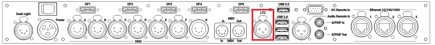
grandMA3 full-size (CRV) and light (CRV) rear panel – LTC

grandMA3 compact (XT) rear panel – LTC
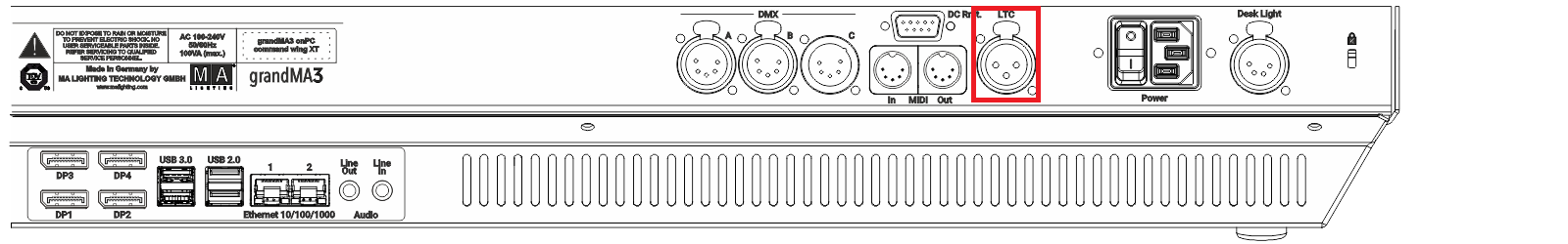
grandMA3 onPC command wing (XT) rear panel – LTC
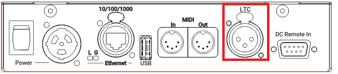
grandMA3 I/O Node rear panel – LTC
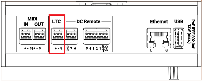
grandMA3 I/O Node DIN-Rail rear panel – LTC
To view the pinout of the XLR and Euroblock connector, refer to the topic Connector Pin Assignment.