Installation
 | Hint: The grandMA3 I/O Node can be connected with the power cable. Only the grandMA3 I/O Nodes DIN-Rail need to be installed on the rail following DIN EN 60715 and the instructions below. |
 | Important: Install the grandMA3 I/O Node DIN-Rail horizontally so that the input terminal is located at the bottom. |
 | Warning: In order for the device to dissipate heat, comply with a minimum distance of 30 mm (approx. 2 inches) above and beneath the grandMA3 I/O Node DIN-Rail. |
- Install the grandMA3 I/O Node DIN-Rail onto the rail.
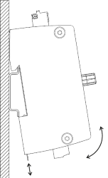
Place the grandMA3 I/O Node DIN-Rail on the rail.
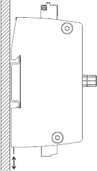
Snap into place
- Build the I/O Node DIN-Rail into the switchboard.
Connections
Section titled “Connections”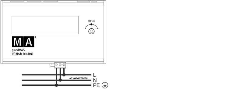
Connect with electrical grid
-or-
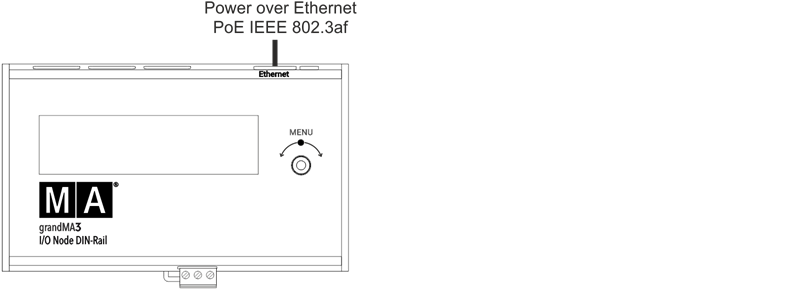
Connect via PoE
| Power | |
|---|---|
| Connector | MC 1.5/ 3-ST1-5.08 |
| Rigid cables | 0.75 mm² - 1.5 mm² (18-16 AWG) |
| Flexible cables | 0.75 mm² - 1.5 mm² (18-16 AWG) Wire end sleeves are permitted. |
| Wire stripping length | 7 mm |
| Tightening torque | 0.22 Nm - 0.25 Nm |
| MIDI & LTC | |
|---|---|
| Connector | FK-MC 0.5/ 3-ST-2.5 |
| Rigid cables | 0.14 mm² - 0.5 mm² (26-20 AWG) |
| Flexible cables | 0.14 mm² - 0.5 mm² (26-20 AWG) Wire end sleeves are permitted. |
| Wire stripping length | 8 mm |
| DC Remote | |
|---|---|
| Connector | FK-MC 0.5/ 7-ST-2.5 |
| Rigid cables | 0.14 mm² - 0.5 mm² (26-20 AWG) |
| Flexible cables | 0.14 mm² - 0.5 mm² (26-20 AWG) Wire end sleeves are permitted. |
| Wire stripping length | 8 mm |